
Gratefully, happily, and amazingly providing solutions for your needs.
Products > Neckerchief Slide Kit > Neckerchief Slide Kit Instructions
Instructions
| Step 1 | |
 |
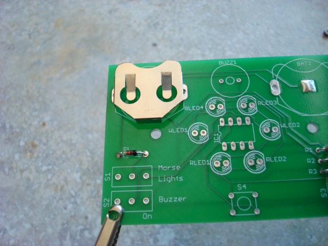
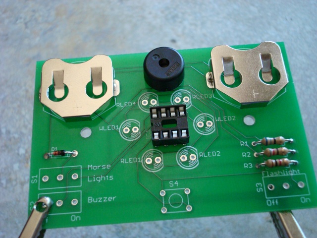
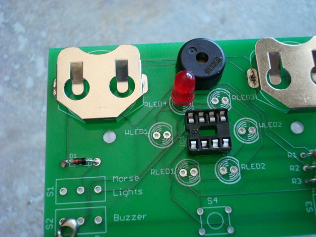
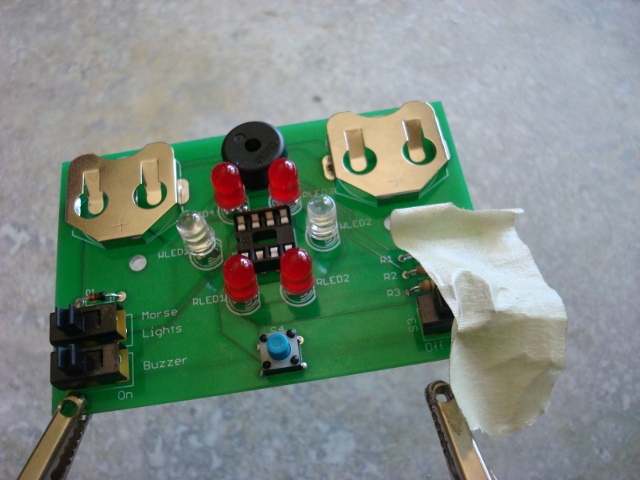
Check your parts against this picture and the back of the instruction manual. |
 |
Make sure that you have all of these tools handy. Clockwise from upper left: Masking tape, scissors, pliers, wire cutters, X-acto knife, soldering iron, helping hands, and solder. |
| Step 2 | |
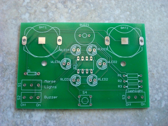 |
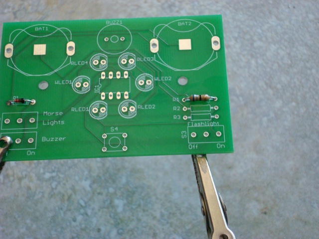
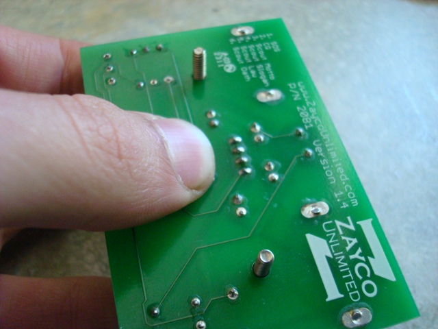
First thing's first, get the board and just take a look at it. I think that it's pretty amazing that can be made. |
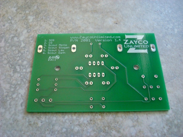 |
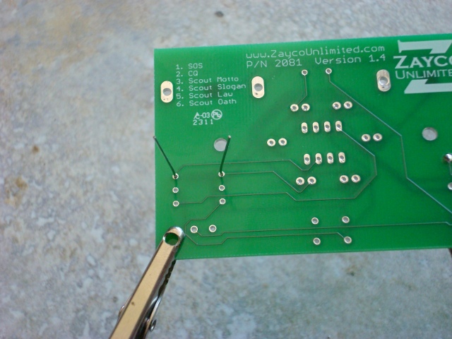
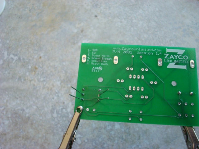
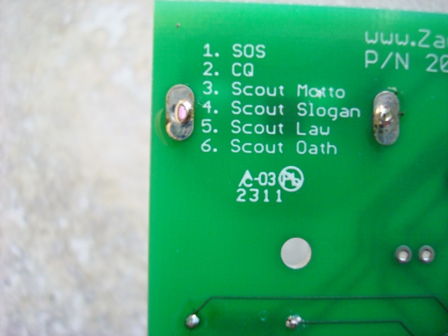
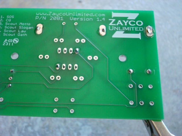
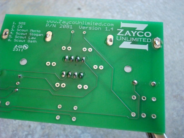
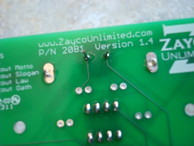
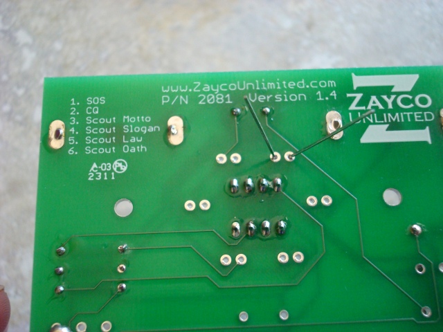
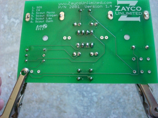
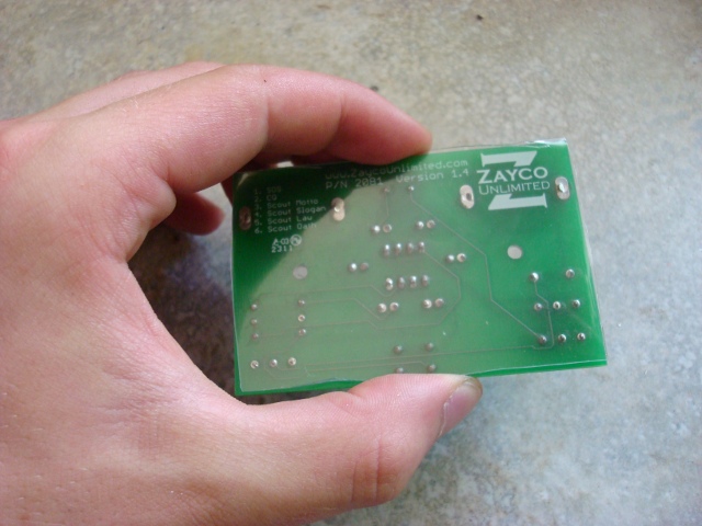
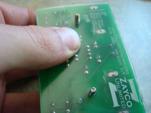
Here is a picture of the back of the board. |
| Step 3 | |
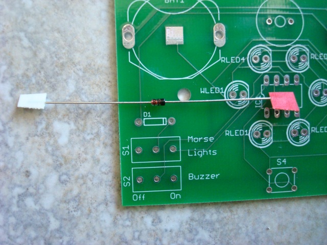 |
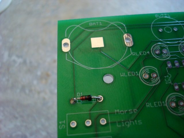
The first part we'll insert is the diode. Diodes are semiconductors, meaning that manufacturers can control the flow of electricity through the part. In the case of the diode, electricity only flows in one direction. Line up the band on the diode with the band on the board, and notice the color of the tape on the ends. The band is on the side with the red tape. |
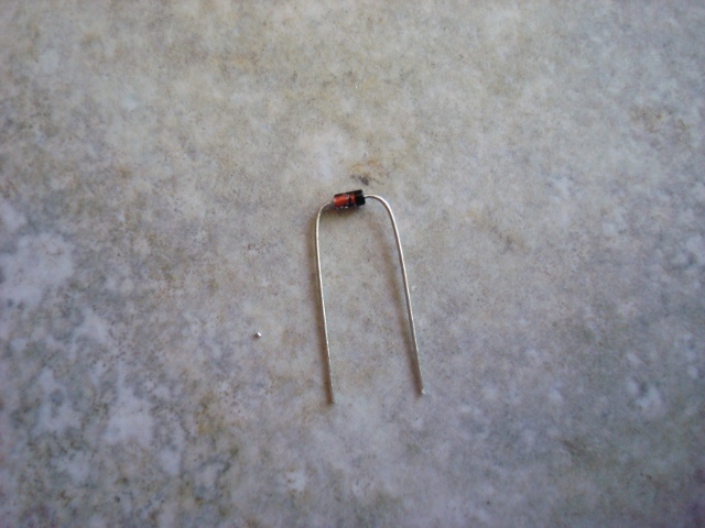 |
Carefully bent the leads of the diode to a right angle and cut off the tape with the wire cutters. |
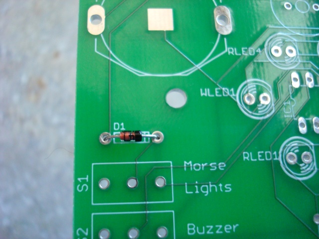 |
Insert the diode into it's place noting the alignment of the bands. |
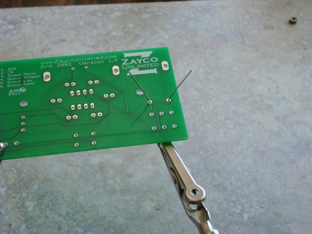 |
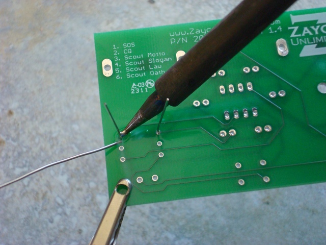
Now flip the board over and bend the leads of the diode out slightly. This is just so the part doesn't fall back out. |
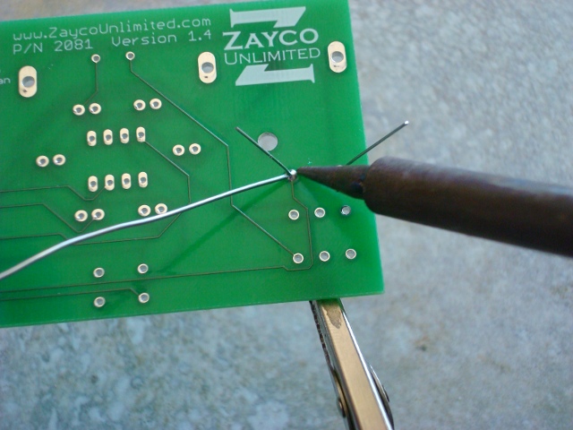 |
Carefully solder the diode now. The Electronics Merit Badge pamphlet is a great resource on how to solder. The pamphlets are a great library and I recommend reading them for any merit badge. |
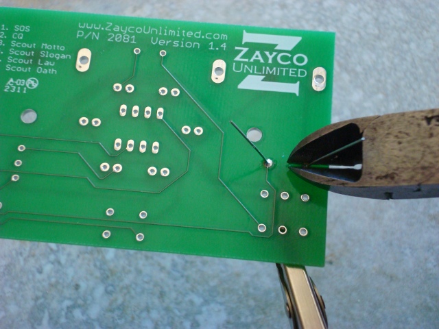 |
Now clip the leads as short as possible. |
 |
The first part is all soldered and done. |
| Step 4 | |
 |
Bend the leads of the first resistor to right angles. This resistor is the one with the blue, gray, black, and gold bands. |
 |
Place this resistor in the space marked R1. Resistors, unlike diodes, can go in either way. I like to put all of the gold bands on the right for neatness sake. |
 |
Flip the board over and make sure the leads are bent out so it doesn't fall through. |
 |
Solder it in there. |
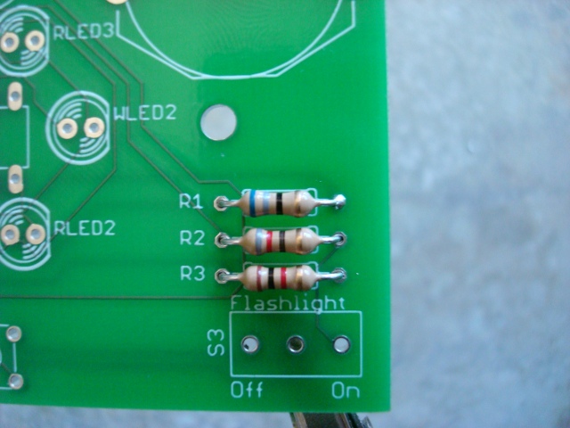 |
You should know the drill by now. Put the resistor with the gray, red, black, and gold bands in the place marked R2, and the one with the brown, black, red, and gold bands where is it is marked R3. |
 |
Solder the last two resistors and clip all of the leads. |
| Step 5 | |
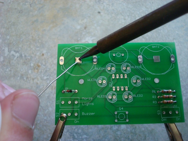 |
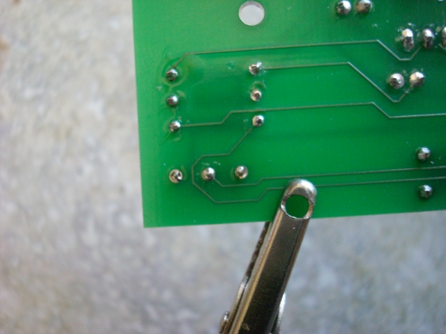
In order to make a good connection with the negative terminal of the batteries you need to apply solder to the pads. Don't add too much or the battery won't fit it, but just enough to make a rounded dome. The surface tension of the solder should do that nicely, just don't play with it too much. |
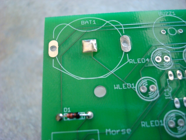 |
This is what the pad should look like in the end. |
 |
The holder should just snap into place. |
 |
Apply ample solder here because is is also a mechanical connection and it needs to hold the batteries. Once this is finished, do the same to the other battery holder. |
| Step 6 | |
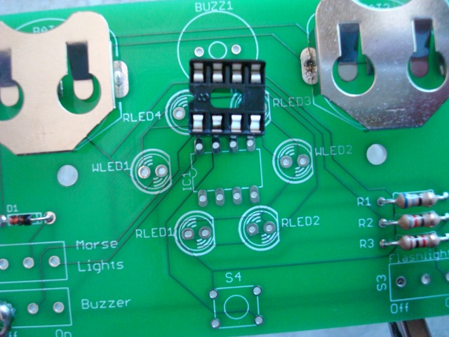 |
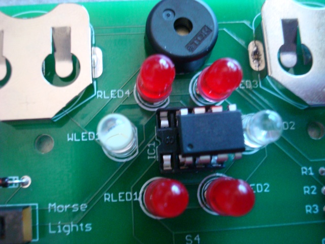
Now we're going to install the IC socket. This makes is a litter friendlier for the microcontroller. Notice the notch on the end and line that up with the notch on the silkscreen. |
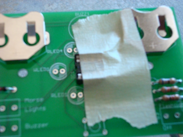 |
I like to keep masking tape handy so I can tape things that won't stay in place. This socket is one of them. Put it in and tape it down. |
 |
When you know that the socket is flat aginst the board solder two opposite corners. |
 |
Now solder the rest of the pins. You don't need to clip them because they're already so short, but I like to give it a try. That finishes up the socket. Just hang on to the actual chip, we'll do that later. |
| Step 7 | |
 |
Now insert the piezoelectric buzzer into BUZ1. It doesn't matter which way you put it in. |
 |
Flip the board over and solder. |
| Step 8 | |
 |
LED stands for Light Emitting Diode. It has polarity meaning it needs to go in one way. There is a flat spot on the rim and that lead is shorter. |
 |
Line the flat spot up with the one on the silkscreen. |
 |
Bend the leads out. |
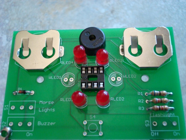 |
Insert the rest of the red LEDs. |
 |
Flip the board over and bend the leads out. |
 |
Now solder all of the LEDs. |
 |
Clip the leads. Don't forget to do the same thing with the white LEDs. I forgot to do them here when I took the pictures. |
| Step 8 | |
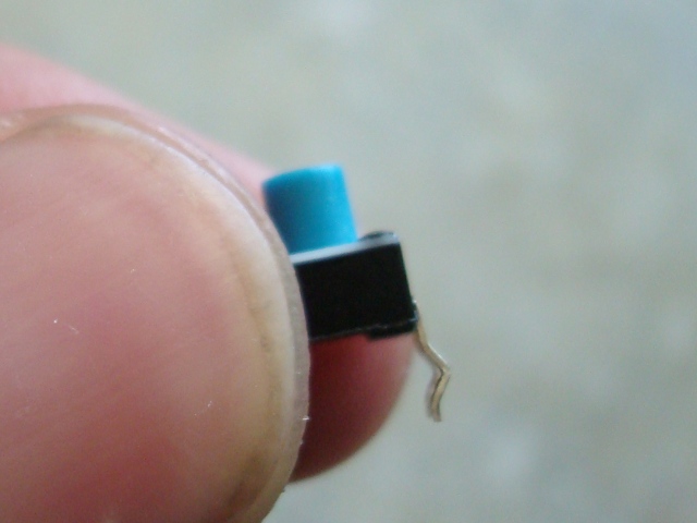 |
Now it's time for the button. Notice that the legs are bent. In order for it to fit well, you need to straighten them. |
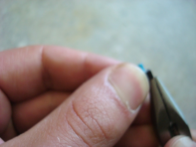 |
Use needle-nose pliers to straighten the legs. There is a sweet spot that will straighten the entire leg at once. |
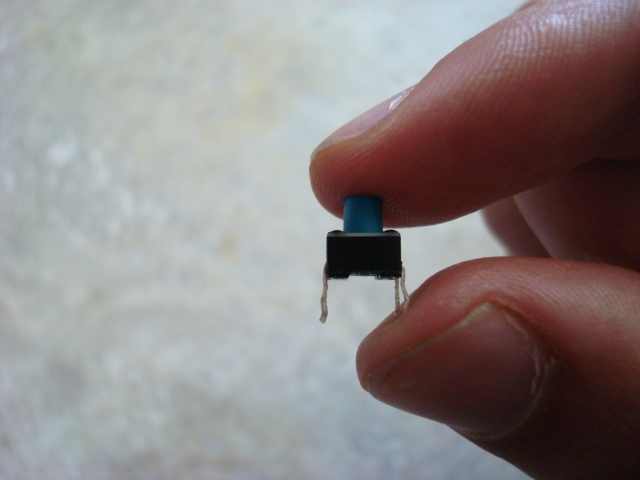 |
The leg on the left has been straightened and the leg on the right still needs to be. |
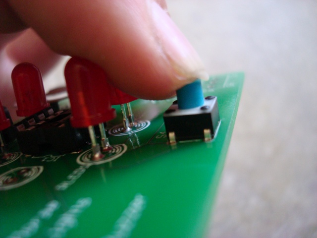 |
Make sure you put the button in so the sides with the legs coming out are on the sides. This should be the only way it fits. |
 |
It may be a good idea to tape the button down, but you may not have to. |
 |
Solder the button in. |
 |
I like to try and clip the leads, but you probably won't be able to get much. |
| Step 9 | |
 |
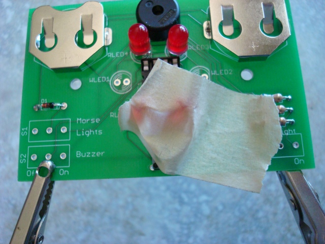
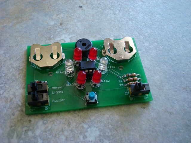
The switches are a little tricky because they're a little loose. Tape them in and try to get them as straight as possible. Use gravity to your advantage here. |
 |
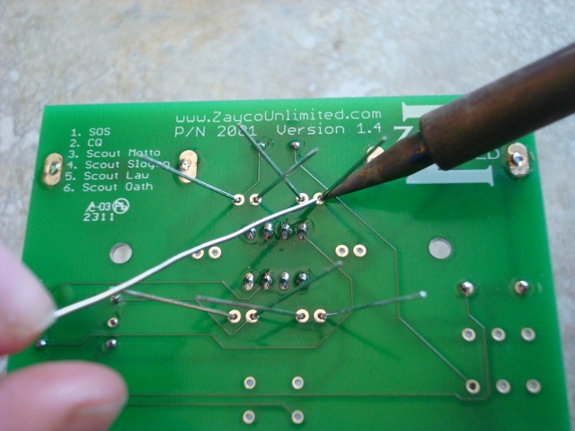
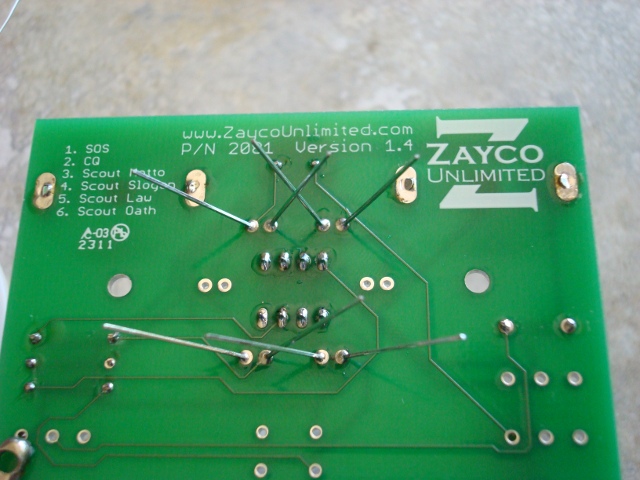
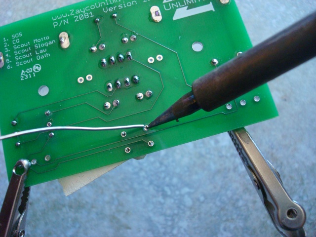
Solder the switches in. |
 |
Tape in the other switch and make sure it is straight. |
 |
Solder the last switch in. |
| Step 10 | |
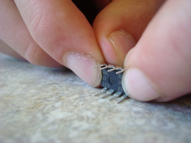 |
In order for the IC to fit nicely in the socket you need to make sure that the pins are straight. Use a flat surface to bend them to the right angle. |
 |
Line up the dimple on the IC to the notch in the socket. Make sure not to put in in backwards or you might ruin the chip. |
 |
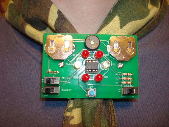
Congratulations, you should be finished soldering now. Don't put the iron away just yet in case you need to troubleshoot. |
 |
Insert the batteries positive (or smooth) side up. Now for the smoke test. Turn on the slide. If it all works, great. Go on to the next step. If not, shut it off fast and please visit the troubleshooting section of our website. |
| Step 11 | |
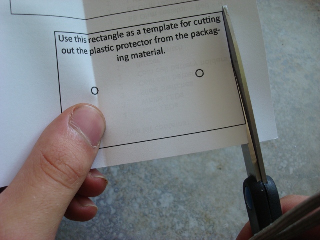 |
Now cut the template for the protector out of the back of the instruction sheet. |
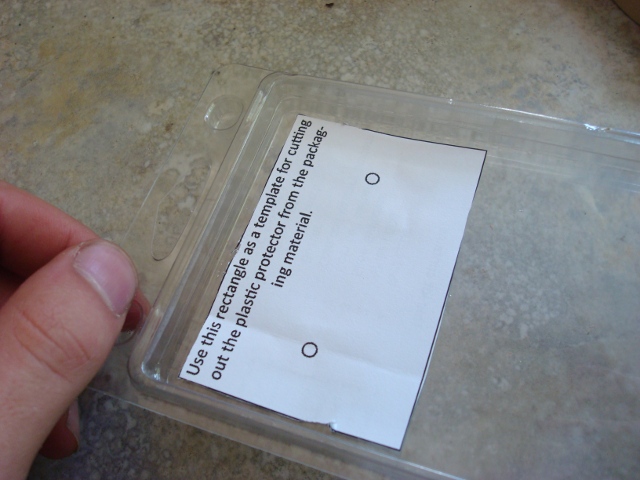 |
Tape the paper template to the front of the clamshell. |
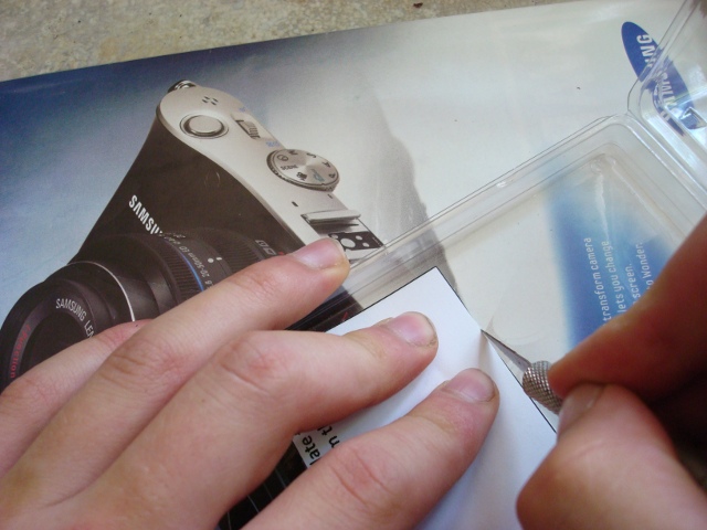 |
Use an X-acto knife to cut the plastic template. Make sure you use the back of a magazine so as to not ruin the table or the knife. |
 |
Check the fit of the protector and trim it. |
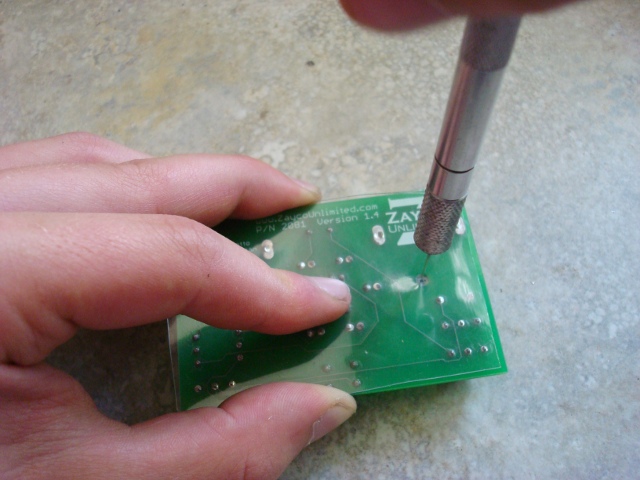 |
Use the X-acto knife to carefully poke the holes for the screws. Twirl it gently with a little pressure until you're through. Clean up the hole with the knife. |
 |
Insert the screws into the board from the front. |
 |
Now place the protector over the screws. |
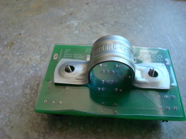 |
Put the clamp on top of that. |
 |
Place the washers over the clamp. |
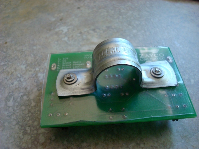 |
And the lock washers on top of those. |
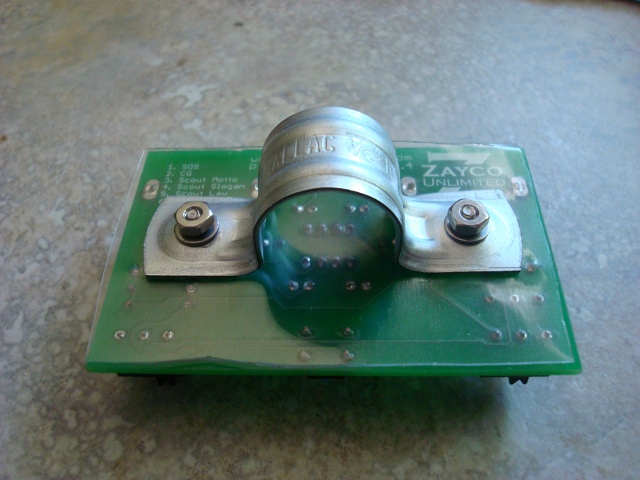 |
Now finger tighten the nuts down. |
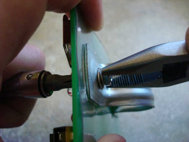 |
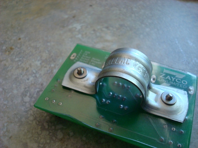
Make sure that everything is centered and posistioned neatly. Using a screwdriver, hold the head of the screw, and use pliers to tighten the nut on the back of the slide. |
| Step 12 | |
 |
Congratulations! You just finished making the coolest neckerchief slide around. Sit back and think about what you just accomplished and then put 'er on, and show 'er off. |